Application Note / 2026-09-05
Six-Axis Robot Dress Pack Routing for CNC Machine Tending
A practical dress pack review follows external cables and pneumatic tubes from their supports to the robot tool, checking component requirements and wrist movement.
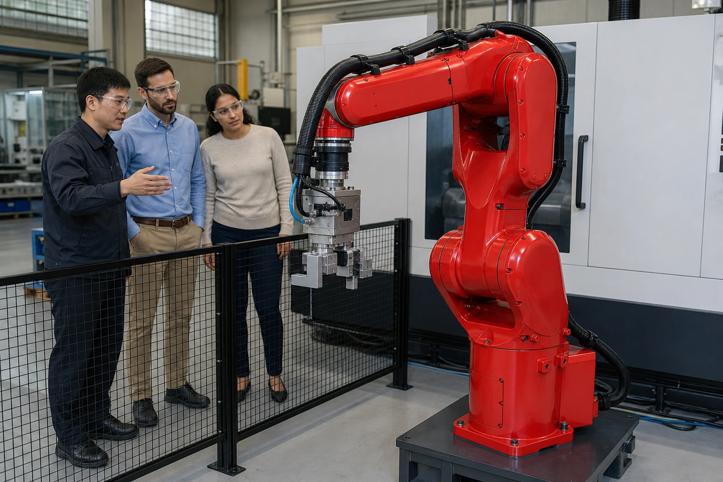 Application scene visualization: AI-generated factory staff and adult visitors review external services on a six-axis robot beside a CNC.
Six-axis robot dress pack routing for CNC machine tending means reviewing the external cables and pneumatic tubes that move with the arm and supply its tool. Check each component's identity, bending and torsion conditions, wrist movement allowance, strain relief, carrier separation and behavior as the tool changes orientation. Use the selected components' documentation and the actual tool arrangement to turn those checks into a useful routing record.
Start with the services that move with the tool
List each external cable or tube, its purpose, part number, connection points and moving segment. Keep the robot arm-to-control-box cable separate: it has its own manufacturer requirements, as illustrated by UR's robot cable documentation.
Follow each tool service to its termination. Relate that connection to the actual CNC loading gripper design, so the review uses the installed tool rather than a generic bundle shown in a catalogue.
Read bending and torsion data separately
A cable that bends repeatedly is not automatically suitable for repeated twisting at a robot wrist. Check the applicable moving-installation conditions, the manufacturer's radius definition, torsion conditions and environment. A radius specified for static installation does not establish the moving requirement. igus CFROBOT2 documentation illustrates how a manufacturer identifies a cable intended for three-dimensional twisting motion.
Review pneumatic tubing separately. The Festo PUN-H-SF data sheet lists minimum and flow-relevant bending radii as different fields, alongside tube size, medium and pressure/temperature conditions. A statement that tubing is suitable for energy chains does not, by itself, provide a wrist torsion allowance.
Follow the route through the wrist to the tool
Look closely at the section between the carrier exit and tool connection. Too little movement allowance can pull on a connector; an overlong loop can catch on the tool or workpiece. Cable migration through the dress pack can also change that allowance. These mechanisms are described in igus guidance on strain relief.
Review the loop, its support and the room needed to bend against the selected assembly instructions and actual tooling. Record the required arrangement instead of copying a clamp position or loop length from another installation.
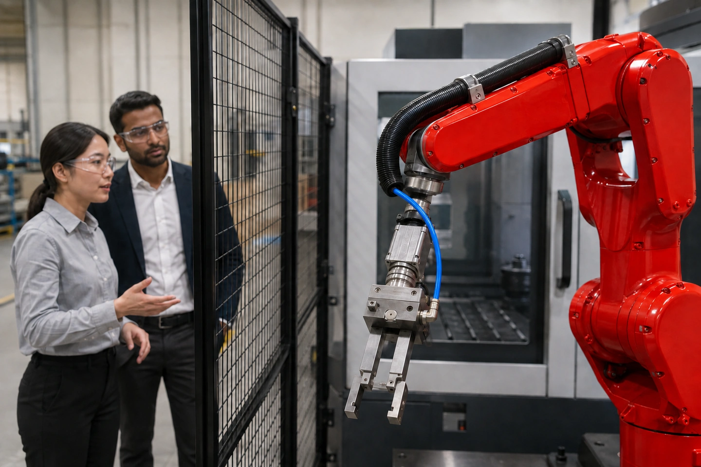 Application scene visualization: generated participants observe a supported wrist-to-tool cable and tube route outside the guarded area.
Check the carrier and the bundle together
Multi-axis carriers can provide bend control, torsion stops and internal separation, as described for igus triflex R. Check these features together with each contained line's requirements and the supplier's filling-clearance guidance. A carrier does not replace the cable or tube data sheet.
Avoid tightly binding mixed moving lines into a rigid bundle. The igus routing guide explains why restrictions and inadequate internal clearance deserve attention when cables and hoses move together.
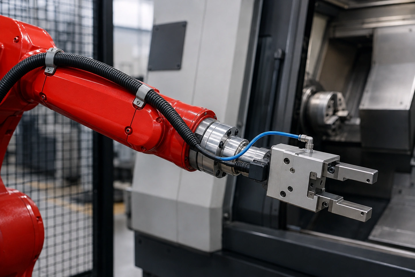 Application scene visualization: supported services reach the empty gripper with visible bending room; the arrangement is illustrative.
Record changes at the required tool orientations
Within the site's established inspection and commissioning arrangements, record pulling, rubbing, snagging, kinking or unexpected migration. Identify the affected segment and retain the relevant layout or photograph with the component-document revision.
| Item / route segment | Component / requirement source | What to check | Observation / action |
|---|---|---|---|
| Electrical service | Enter part/data sheet | Bend and torsion conditions | Enter finding/action |
| Pneumatic service | Enter tube/data sheet | Radius and operating conditions | Enter finding/action |
| Wrist-to-tool connection | Enter layout/manual | Loop, support, connector stress | Enter finding/action |
| Carrier and separation | Enter carrier/manual | Clearance and movement | Enter finding/action |
| Changed tooling or route | Enter revision/photo | Pulling, rubbing or migration | Enter finding/action |
When the tooling or service route changes, connect the findings to the six-axis robot payload checklist and one-CNC reach study checklist. Carry unresolved observations into the CNC machine tending acceptance test plan.
Frequently asked questions
What belongs in a robot dress pack for CNC tending?
The external cables and pneumatic tubes supplying the tool, together with their carrier, supports and terminations. The exact list comes from the installed application.
Is a flexible cable automatically suitable for wrist torsion?
No. Check whether its documentation covers the required twisting motion and operating conditions, as well as bending.
How much cable or hose allowance should remain at the wrist?
Use the selected assembly instructions and actual tool movement. The loop needs room to move without pulling connections or catching on surrounding equipment; there is no universal length for every installation.
When should a dress pack routing review be repeated?
Revisit it after changes to tooling, cables, tubing, support or routing, and when observations reveal wear, migration or interference. Keep the revised arrangement linked to its component records.
Discuss the arrangement for your CNC
For single-machine CNC tending, prepare the robot/tool arrangement, cable and tube list, component data sheets and clear layout photos. Share them with QIXING to discuss your CNC tending layout.