Application Note / 2026-09-01
CNC Machine Tending Reach Study Checklist: Pick Points, Chuck Pose and Clearance
A reliable one-CNC reach study starts with measured project geometry and a traceable coordinate basis, then retains reproducible simulation evidence and physical route checks.
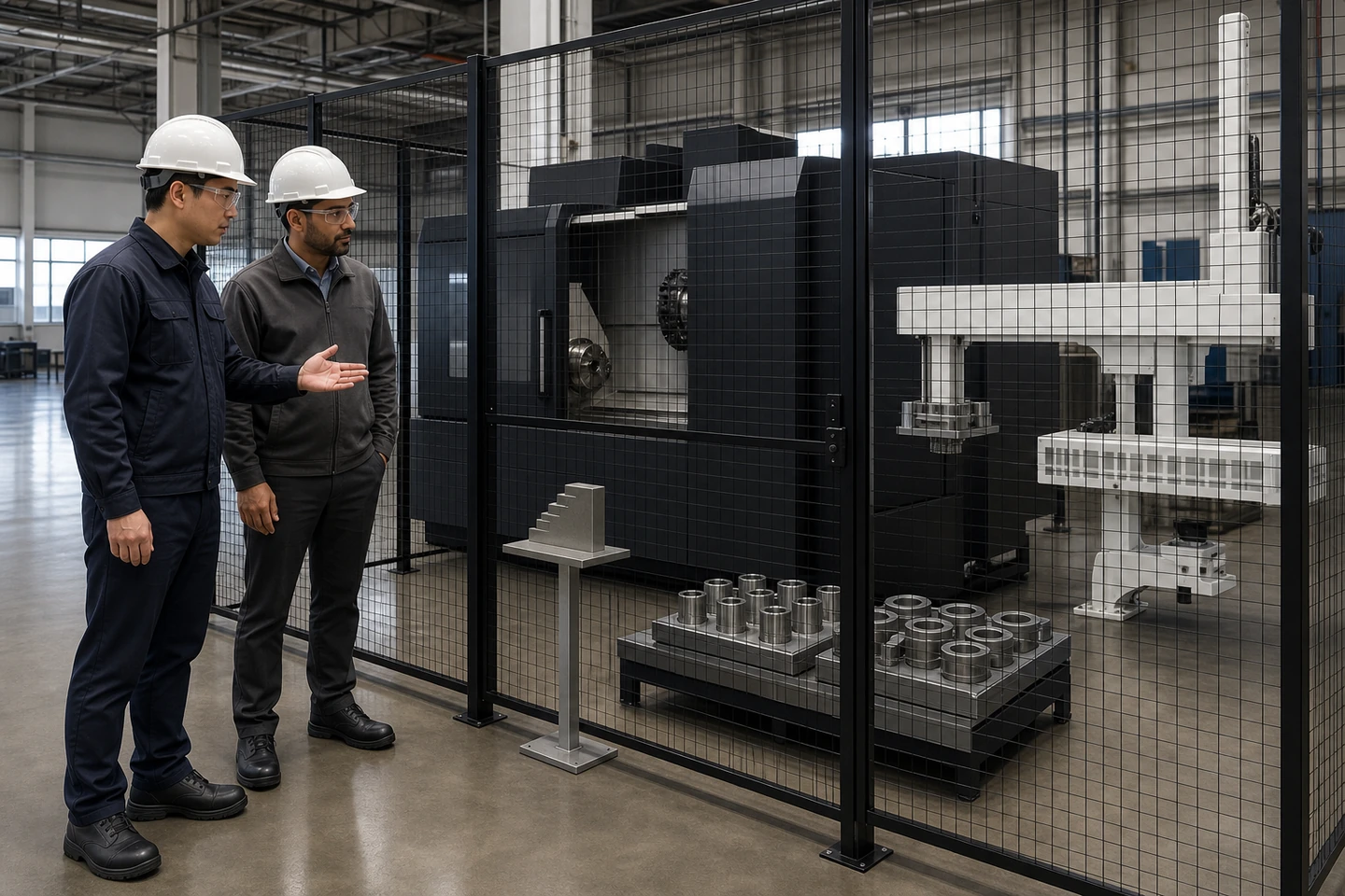 Application scene visualization / project reach remains subject to measured geometry, reproducible analysis and physical validation
A CNC machine tending reach study needs a named coordinate basis, measured pickup and handoff points, the CNC opening and internal envelope, the complete end-effector-plus-workpiece envelope, configuration-specific axis definitions, categorized clearances, and reproducible validation evidence. Published stroke data or a generic simulation screenshot cannot decide whether a robot reaches the actual chuck. A project conclusion can be considered only after the real geometry has been measured, the relevant states have been modelled with traceable assumptions, and the route has been checked physically with the actual project inputs; no single step proves compatibility or safety.
Define what the reach study will and will not decide
Set the study boundary before collecting dimensions: one CNC machine, one measured material route and one named project coordinate basis. State which geometry revision, end-effector configuration and workpiece states are included. Keep model selection, machine compatibility, collision-free operation, safeguarding and acceptance outside the conclusion unless their separate project processes provide the necessary evidence.
The single-machine material path can help identify raw pickup, CNC load and unload, and finished return as conceptual handoffs. Use broader machine, workpiece and site inputs to collect the underlying machine opening, workpiece and layout information. Neither page supplies measured project coordinates.
Freeze the coordinate basis and every geometry revision
Every point needs a stated coordinate basis, unit, measurement source and geometry revision. If a transformation is used between the layout, CNC, robot and tooling files, retain that transformation and mark any unresolved assumption. Otherwise, a point can look precise while referring to a different origin, axis direction or revision.
Minimum traceability for a measured point
For each entry, preserve who or what supplied the measurement, the date or controlled revision, the operating state represented and the file in which it is used. Do not invent a reference zero, coordinate value or approach distance. An open field should remain an open project input rather than being copied from a conceptual drawing.
Measure pickup, load, unload, placement, approach and retreat points
Measure the points required by the actual sequence: raw-part pickup, CNC load, finished-part unload, finished or reject placement, and the approach and retreat points around each handoff. The number and arrangement of points come from the real process; this checklist does not prescribe coordinates or a validated route.
| Route element | Measured point or pose | Coordinate basis | Measurement source | Geometry revision | Operating state | Open assumption |
|---|---|---|---|---|---|---|
| Raw-part pickup | Project entry | Project entry | Project entry | Project entry | Project entry | Project entry |
| CNC load | Project entry | Project entry | Project entry | Project entry | Project entry | Project entry |
| Finished-part unload | Project entry | Project entry | Project entry | Project entry | Project entry | Project entry |
| Finished/reject placement | Project entry | Project entry | Project entry | Project entry | Project entry | Project entry |
| Approach/retreat points | Project entry | Project entry | Project entry | Project entry | Project entry | Project entry |
Capture the CNC opening, chuck pose and moving access states
The machine model should include the opening in the states relevant to tending, not just the external outline. Record the door opening, spindle and chuck or fixture pose, projection into the workspace, turret or tool interference where applicable, roof clearance, service panels and other moving or access envelopes.
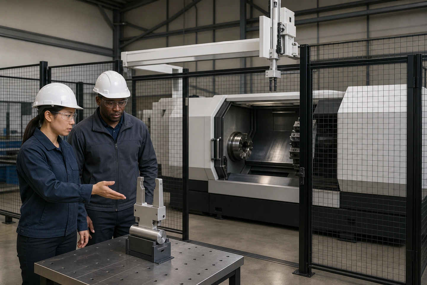 Application scene visualization / actual geometry and reach remain project-specific
An external CNC model name or cabinet outline does not establish the chuck position or internal access. Interface states belong to their own design work, while configuration comparison and architecture selection remain separate decisions. This checklist records geometry needed for the study; it does not select an architecture or design I/O.
Include the complete end-effector and workpiece envelope
Model the full moving assembly in every relevant pose: gripper body, fingers, adapters, sensors and one representative workpiece. Include the farthest approach and the least-favourable workpiece centre of gravity as project inputs. Checking only the carriage, wrist centre or nominal part shape can omit the component that actually comes closest to the door, chuck, tooling or guarding.
Do not create end-effector dimensions, pose angles, payload margin or a collision-free route from this instruction. The complete assembly must come from the controlled project configuration and representative part data.
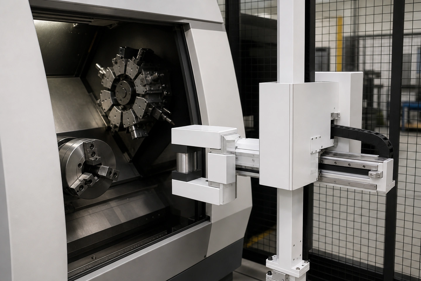 Application scene visualization / final reach and clearance require measured project evidence
Separate published axes from project-available travel
Axis information should state the axis direction, its reference, the published or configured stroke, and the travel actually available for the measured route as separate fields. QIXING public pages show that axis sets and stroke fields differ by configuration, so a value cannot be transferred from one configuration to another or treated as usable project travel.
Use the QR4-1600 configuration-specific axis reference, QR4-2400 configuration-specific axis reference and QR4-3000 configuration-specific axis reference only for their respective published fields. The checklist does not convert those fields into reach margin, overtravel, software limits, acceleration distance or compatible machine size.
Review clearances by category, not as one generic gap
Clearance review should separately cover the CNC opening and internal hardware; chuck, fixture, turret and tooling; doors and covers; raw, finished and reject positions; supporting structure and overhead space; guarding; operator replenishment; maintenance access; and the abnormal-recovery route. A visible geometric gap is not automatically a safety clearance.
| Clearance category | Geometry/state included | Measurement or model source | Open assumption | Separate project review |
|---|---|---|---|---|
| CNC opening and internal hardware | Project entry | Project entry | Project entry | Project entry |
| Chuck/fixture/turret/tooling | Project entry | Project entry | Project entry | Project entry |
| Material positions and structure | Project entry | Project entry | Project entry | Project entry |
| Guarding and replenishment | Project entry | Project entry | Project entry | Project entry |
| Maintenance and recovery access | Project entry | Project entry | Project entry | Project entry |
This categorization is not a risk assessment, guarding design or compliance record. It supplies geometry and open questions for the responsible project reviews; it cannot provide a safety distance, stopping performance or safe-pass result.
Retain reproducible simulation evidence and complete a physical check
If simulation is used, retain the machine, layout, end-effector and workpiece file revisions; coordinate transformations; included operating states; assumptions; and the owner of unresolved inputs. A screenshot without those records is difficult to reproduce and cannot show whether the correct geometry was used.
Simulation remains a planning result until the route is checked with the actual CNC, tooling, workpiece and physical states. A physical demonstration alone also cannot prove that every required state, pose or assumption was covered. Only after measured inputs, reproducible simulation evidence and project-specific physical verification have been completed can the responsible project team judge the configuration; even then, reach evidence does not by itself establish safety acceptance.
Use downstream acceptance evidence planning when the project is ready to define tested configuration, evidence owners and open decisions. This reach-study page does not create acceptance criteria or results.
Fillable one-CNC reach-study input matrix
| Input group | Point or envelope | Coordinate basis / operating state | Measurement source | Geometry revision | Included tool and part pose | Open assumption | Validation evidence |
|---|---|---|---|---|---|---|---|
| Raw pickup | Project entry | Project entry | Project entry | Project entry | Project entry | Project entry | Project entry |
| CNC load / unload | Project entry | Project entry | Project entry | Project entry | Project entry | Project entry | Project entry |
| Finished / reject placement | Project entry | Project entry | Project entry | Project entry | Project entry | Project entry | Project entry |
| Approach / retreat | Project entry | Project entry | Project entry | Project entry | Project entry | Project entry | Project entry |
| CNC and moving envelope | Project entry | Project entry | Project entry | Project entry | Project entry | Project entry | Project entry |
Leave coordinates, dimensions, clearance values, stroke margins, simulation results and compatibility status blank until controlled project evidence exists. Mark each row as measured, pending measurement, pending model revision, pending simulation review or pending physical check.
Frequently asked questions
What is a CNC machine tending reach study checklist?
It is a controlled list of the measured points, coordinate basis, CNC and moving envelopes, configured axes, clearance categories, assumptions and validation evidence needed to study one CNC route. It is not a robot recommendation or compatibility report.
Can a published axis stroke prove that a robot reaches the chuck?
No. A published stroke belongs to a stated configuration. Project reach depends on the measured coordinate basis, chuck pose, approach route, complete end-effector and workpiece envelope, available travel and validation evidence.
What is the difference between a geometric gap and a safety clearance?
A geometric gap is a measured or modelled separation in a stated condition. Whether that separation is sufficient for safeguarding requires a separate project risk assessment and safety review; this checklist does not make that determination.
What evidence should be retained when simulation is used, and why is a physical check still required?
Retain all geometry revisions, coordinate transformations, included states, assumptions and unresolved owners so the study can be reproduced. Then check the route with the actual CNC, tooling, workpiece and physical states because simulation alone cannot prove compatibility or safety.
Sources and use boundaries
This article uses only QX014-F01 through QX014-F06, QX-FCT-20260831-002, QX-FCT-20260826-003, QX-FCT-20260826-004, QX-FCT-20260826-005, QX-FCT-20260830-002 and QX-FCT-20260826-007. QIXING public pages support bounded project inputs and configuration-specific axis references. OSHA material supports only general application-specific path, pose and maximum-space terminology; it does not establish global compliance or a project safety result.
Submit the measured reach-study inputs
Prepare the actual CNC layout and opening, chuck or fixture pose, raw and finished part data, material positions, complete end-effector envelope, project coordinate basis and current geometry revisions. Then submit the reach-study input package for an application review. The review does not promise a model, reach result, collision-free path or compatibility outcome.