Application Note / 2026-09-03
Six-Axis Robot Payload Checklist for CNC Machine Tending: Mass, CoG and Inertia Inputs
A six-axis payload review needs each physically possible flange-load case, the complete moving wrist assembly, mass, CoG, inertia and manufacturer-specific evidence.
 Application scene visualization / actual load limits and suitability require the selected manufacturer's current data and project review: fully generated, non-specific China-based factory staff and adult international visitors discuss a six-axis robot, complete gripper and supported representative part beside one safeguarded CNC.
A six-axis robot payload checklist for CNC machine tending should document every physically possible flange-load case, the complete moving wrist assembly, total mass, center of gravity in the selected manufacturer’s coordinate system, required inertia representation, installed orientation, manufacturer-analysis evidence and the active payload state used during pickup, transport and release. Workpiece weight alone is not enough, and a completed sheet does not select a robot or prove payload margin, reach, compatibility, safety or production readiness.
List the real flange-load cases before comparing any robot
Start with the states the application can actually create: empty tool, blank held, finished part held, and only those dual-grip or auxiliary-tool combinations that are physically possible. Keep impossible or unconfirmed combinations out of the total rather than inventing a conservative-looking number.
| Load case | Workpiece state | Physically possible? | Installed orientation | Evidence status |
|---|---|---|---|---|
| Empty tool | No workpiece held | Project input | Project input | Confirmed / site verification / manufacturer decision |
| Blank held | Representative blank | Project input | Project input | Confirmed / site verification / manufacturer decision |
| Finished part held | Representative finished part | Project input | Project input | Confirmed / site verification / manufacturer decision |
| Combined or auxiliary-tool state | Project-defined state | Project input | Project input | Confirmed / site verification / manufacturer decision |
The gantry or six-axis robot for CNC loading article provides architecture context, while the six-axis payload and reach selection overview offers broader navigation. Numeric statements from that overview are not facts for this checklist and are not carried into the load package.
Build the complete moving wrist assembly
For each case, include every component carried by the robot flange: the workpiece, gripper body, fingers, mounting plate or adapter, quick-change components, sensor housings and other moving hardware. Moving hose or cable effects should be identified for review under the selected manufacturer’s process rather than silently omitted.
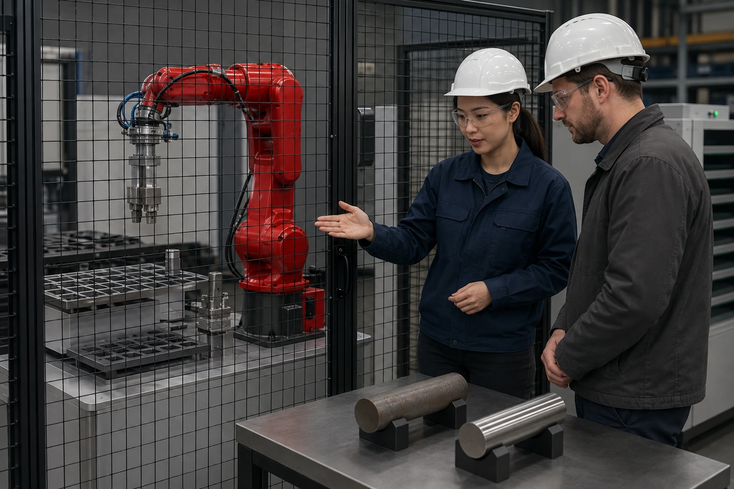 Application scene visualization / actual load cases and component data remain project-specific: the generated adults are conducting a technical review outside the safeguarded area. The image is not a real customer visit, approved robot selection, rating plate, calculator result, delivery or endorsement.
Stationary external equipment should not be counted as a flange load without project evidence. Conversely, a moving component should not disappear from the package because it is small or difficult to measure. Use CNC loading gripper design inputs for mechanical gripper engineering; this page includes the gripper only to define the complete moving load and does not design fingers, force, sensors or service life.
Record mass and center of gravity for every case
Total mass and center of gravity are separate inputs. Record mass from a measured or controlled source, then record CoG coordinates in the coordinate system and units required by the selected robot manufacturer. Retain the installed orientation and the source or derivation used to obtain the CoG.
Mass alone cannot show how a load is distributed relative to the wrist. The checklist therefore keeps CoG values, origin, axes and orientation explicit. It does not estimate coordinates or uncertainty, and it does not transfer one manufacturer’s coordinate convention or payload curve to another robot.
Provide inertia in the representation the manufacturer requires
Inertia may be required as principal moments or as an inertia matrix about a specified origin and axes, depending on the selected manufacturer. Record the required representation and retain its measurement or derivation source. Do not assume that all controllers use the same convention.
If an inertia value is zero, default or unknown, label it exactly that way and keep it unvalidated. A software default is not automatically measured, calculated or accepted load data, and the article does not invent inertia components, torque or acceleration values.
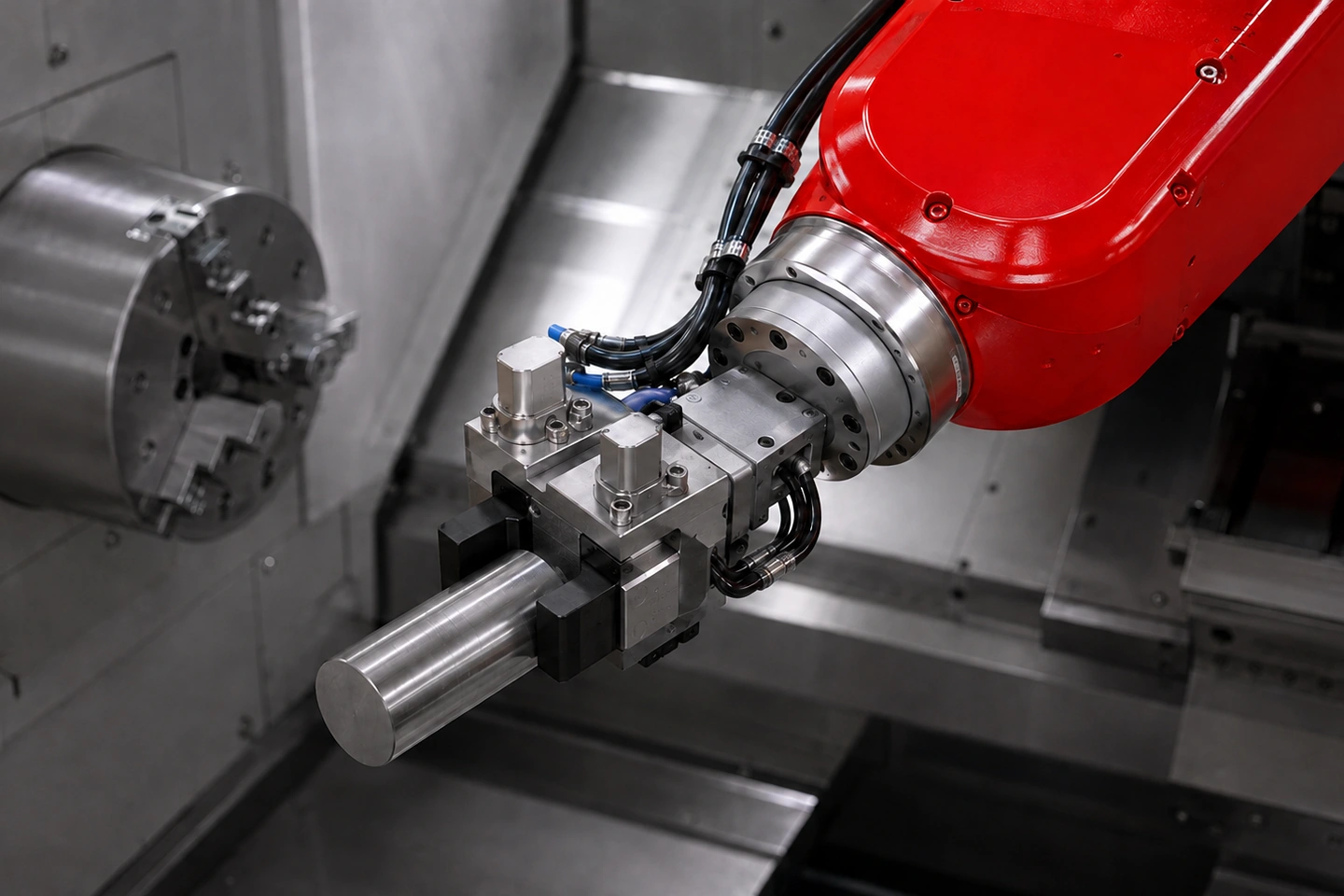 Application scene visualization / not payload-capacity or performance proof: this no-people technical detail contains no text, numbers, CoG symbols, force arrows, brand-like marks or engineering-drawing styling. It does not prove margin, compatibility or safety.
Run manufacturer-specific load checks and preserve evidence
Each real load case should be checked using the selected manufacturer’s current manual, load diagram and approved calculation or validation tool. Preserve the manual or tool version, all inputs, output, relevant pose, orientation, motion or acceleration conditions required by that manufacturer, and unresolved flags.
UR and KUKA references in the fact pack demonstrate that mass, CoG, inertia and analysis requirements are manufacturer-specific. Their load curves, coordinate systems, limits, commands and results cannot be applied to QIXING or another robot. A static diagram or software output is also not a general safety, accuracy, compatibility or cycle-time pass.
The one-CNC reach study checklist addresses measured positions and clearance, not flange-load capacity. Keep reach and payload packages linked by configuration and revision, but do not use one as proof of the other.
Reconcile reviewed data with installed tooling and active payload states
The reviewed definition must match the tooling actually installed and the robot program’s active payload state during pickup, transport and release. Record which load case is intended at each state and which evidence shows that the installed fingers, adapter, sensor, cable routing and workpiece correspond to the reviewed version.
Any change to fingers, adapter, quick-change, sensor, cable routing or workpiece state is a controlled input change that requires rechecking under the selected manufacturer’s process. This article does not supply controller commands, commissioning steps or acceptance thresholds for an unspecified robot.
Use the CNC machine tending acceptance test plan for downstream project validation planning. The payload data package prepares inputs; it is not a test result, commissioning record or production release.
Fillable six-axis robot payload data matrix
| Load case | Workpiece state | Complete moving tool components | Total mass source | CoG coordinates/system/orientation | Inertia representation/source | Manufacturer manual/tool version | Active program state | Open item/owner |
|---|---|---|---|---|---|---|---|---|
| Empty tool | Project input | Project input | Project input | Project input | Project input | Project input | Project input | Project input |
| Blank held | Project input | Project input | Project input | Project input | Project input | Project input | Project input | Project input |
| Finished part held | Project input | Project input | Project input | Project input | Project input | Project input | Project input | Project input |
| Physically possible combined state | Project input | Project input | Project input | Project input | Project input | Project input | Project input | Project input |
Do not prefill mass, CoG, inertia, torque, acceleration, margin, controller commands, model limits, compatibility or pass/fail results. Separate confirmed data, site verification and manufacturer or project decisions.
Frequently asked questions
Is workpiece weight alone enough to select a six-axis robot?
No. The review also needs the complete moving tool assembly, total mass, CoG, inertia, orientation, real load cases and manufacturer-specific analysis. Even that complete package is an input to selection, not a selection result.
Should hoses and cables be included in the payload review?
Moving hose or cable effects should be identified for manufacturer review rather than silently omitted. The project must determine how they are represented; this checklist does not assign forces or a universal calculation method.
Can UR or KUKA payload curves be applied to a QIXING robot?
No. Those sources illustrate manufacturer-specific data and analysis requirements. Their curves, limits, coordinate conventions, commands and results must not be transferred to a QIXING robot or another manufacturer.
Does a completed payload sheet prove compatibility or production readiness?
No. It records the load inputs and evidence needed for review. Robot selection, reach, compatibility, safety, accuracy, cycle time and production release require their own project evidence and responsible decisions.
Sources and use boundaries
This article uses only QX020-F01 through QX020-F06, QX-FCT-20260903-005, QX-FCT-20260903-007 and QX-FCT-20260828-001. Manufacturer references support general, manufacturer-specific load-data requirements; they do not publish a QIXING limit or establish suitability for a project.
Submit the payload data package
Prepare every physically possible load case, component list, measured or derived mass, CoG and inertia data, installed orientation, current manufacturer manual or tool version, active payload states, evidence files and unresolved items. Then submit the six-axis payload data package for review alongside the actual single-machine CNC tending application. The review does not promise a robot recommendation, payload margin, compatibility, cycle time, accuracy or production release.