Application Note / 2026-08-30
CNC Machine Tending Acceptance Test Plan: Normal Cycles, Fault Recovery and Handover Evidence
An acceptance plan defines what configuration will be tested, what evidence will be captured and who owns each decision. It does not supply universal criteria or claim that a cell has passed.
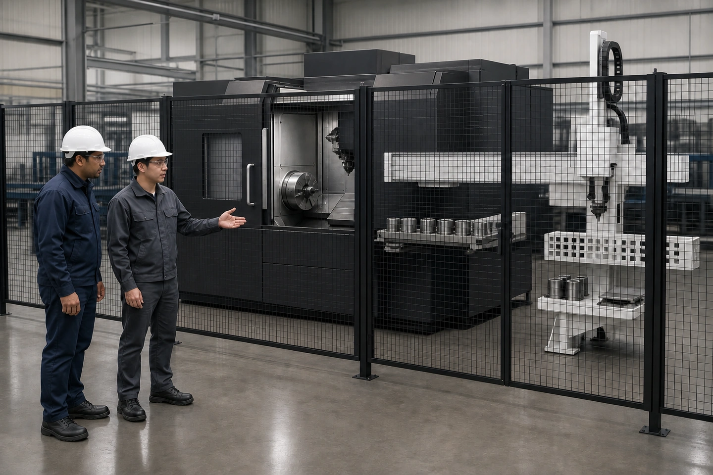 Application scene visualization / final test scope and criteria remain project-specific
A CNC machine tending acceptance test plan should define seven evidence sections before any run: the tested configuration and owners, workpiece presentation, gripping and end-effector state, the normal cycle using actual CNC signals, abnormal scenarios and restart reconciliation, safeguarding evidence, and production handover records. The plan says what will be tested and captured; it is not an acceptance result, universal FAT/SAT specification or production-release decision.
Define the tested configuration and ownership first
Acceptance evidence is meaningful only when it is tied to a known configuration. Record the actual CNC and interfaces, representative workpieces, rough and finished states, material positions, safeguarding boundary, utilities and environmental conditions. Name the parties responsible for executing each section, verifying evidence and resolving open items.
| Configuration field | Confirmed configuration or open input | Evidence source | Execution owner | Verification owner |
|---|---|---|---|---|
| CNC machine and installed interfaces | ______ | ______ | ______ | ______ |
| Representative workpieces | ______ | ______ | ______ | ______ |
| Raw and finished states | ______ | ______ | ______ | ______ |
| Material positions and route | ______ | ______ | ______ | ______ |
| Safeguarding boundary | ______ | ______ | ______ | ______ |
| Utilities and site conditions | ______ | ______ | ______ | ______ |
| Unresolved project decision | ______ | ______ | ______ | ______ |
Use CNC automation site data to collect the underlying machine, workpiece and site inputs. This plan begins after those inputs exist. It does not invent an agreed specification, witness, sample size, acceptance criterion or result.
Plan workpiece-presentation evidence
Identify raw, finished and reject locations, nest identity, permitted orientation, replenishment side and the allowed state at every position. During the test, compare the physical workpiece and nest states with the selected control state.
| Presentation checkpoint | Planned state | Physical evidence to capture | Control-state evidence | Open action |
|---|---|---|---|---|
| Raw-part location and identity | ______ | ______ | ______ | ______ |
| Finished-part location and identity | ______ | ______ | ______ | ______ |
| Reject/unknown-part route | ______ | ______ | ______ | ______ |
| Permitted orientation | ______ | ______ | ______ | ______ |
| Replenishment side | ______ | ______ | ______ | ______ |
| Remaining material | ______ | ______ | ______ | ______ |
This section cannot establish pallet capacity, nest count, automatic part recognition or zero-mix performance. For wider context, use part identity and state reconciliation, but do not adopt a two-machine architecture in this plan.
Plan gripping and end-effector evidence
For the tested workpieces, record rough and finished gripping surfaces, orientation, the complete end-effector condition, contamination, machine clearances, gripping confirmation, loss-of-part detection, cleaning and the agreed safe-recovery boundary. Use actual sample parts rather than a generic part description.
| Gripping evidence item | Tested setup/state | Observation or signal | Result location | Open item |
|---|---|---|---|---|
| Rough/finished gripping surfaces | ______ | ______ | ______ | ______ |
| Orientation and location | ______ | ______ | ______ | ______ |
| Complete end-effector condition | ______ | ______ | ______ | ______ |
| Chips/coolant or other contamination | ______ | ______ | ______ | ______ |
| Machine and tooling clearance | ______ | ______ | ______ | ______ |
| Gripping confirmation | ______ | ______ | ______ | ______ |
| Loss-of-part response and recovery | ______ | ______ | ______ | ______ |
A cylinder or actuator position alone does not prove correct gripping. This section also cannot supply jaw force, sensor thresholds, pickup tolerance, payload margin, gripping accuracy or tooling life. See gripping and end-effector evidence for the specialist engineering background without importing unverified values.
Map normal-cycle evidence with actual machine signals
The normal-cycle section should follow the real machine-tending boundary: machining complete, spindle/door/chuck states, robot approach, unload, cleaning if required, load, clamp confirmation, safe retreat, door close and cycle start. For every checkpoint, record the start condition and completion evidence from the actual machine.
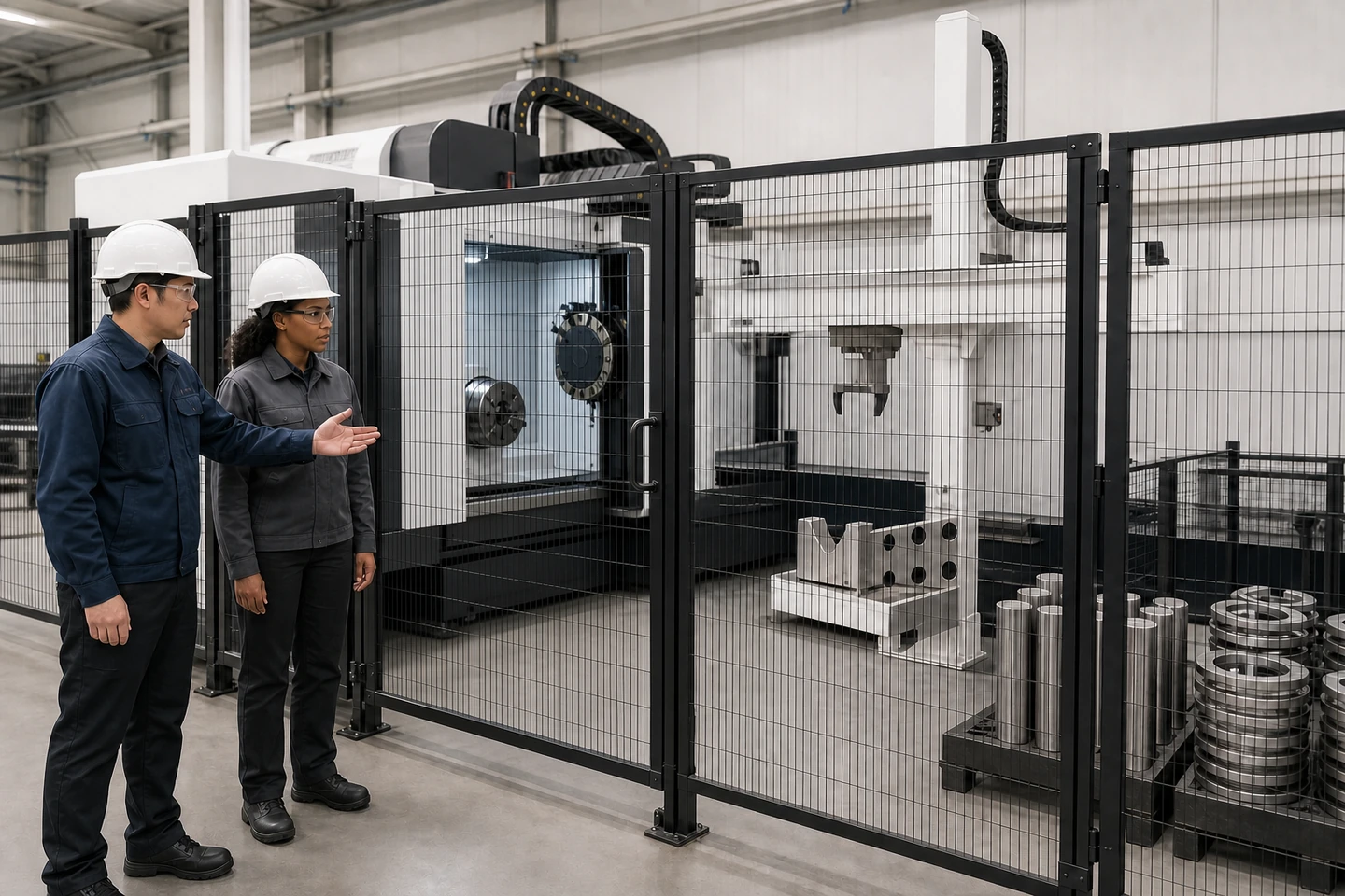 Application scene visualization / final test scope and criteria remain project-specific
| Normal-cycle checkpoint | Start condition | Actual completion evidence | Record owner | Status |
|---|---|---|---|---|
| Machining complete | ______ | ______ | ______ | ______ |
| Spindle, door and chuck state | ______ | ______ | ______ | ______ |
| Robot approach and unload | ______ | ______ | ______ | ______ |
| Cleaning, if required | ______ | ______ | ______ | ______ |
| Load and clamp confirmation | ______ | ______ | ______ | ______ |
| Safe retreat and door close | ______ | ______ | ______ | ______ |
| Cycle-start handoff | ______ | ______ | ______ | ______ |
Use representative parts and repeated trials against a project-defined boundary. The map the full machine-tending cycle article helps identify checkpoints, but no cycle time, trial count, throughput, uptime or production release may be inferred here.
Define abnormal scenarios and reconcile state before restart
The plan should include missing material, empty grip or loss of part, a door/chuck or machine-state fault, pause/restart and a known reject route. After each stop, reconcile the CNC, gripper, nests and workpieces before deciding whether the next step is manual review, a project-defined recovery action or another test.
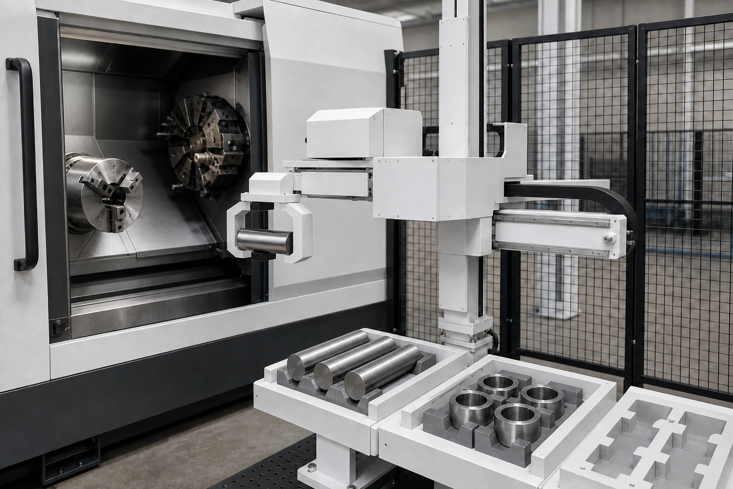 Application scene visualization / final test scope and criteria remain project-specific
| Abnormal-test item | Initial state | Expected safe/project response to verify | Reconciliation before restart | Evidence owner |
|---|---|---|---|---|
| Missing material | ______ | ______ | ______ | ______ |
| Empty grip/loss of part | ______ | ______ | ______ | ______ |
| Door/chuck or machine-state fault | ______ | ______ | ______ | ______ |
| Pause and restart | ______ | ______ | ______ | ______ |
| Reject route | ______ | ______ | ______ | ______ |
| Machine/gripper/nest/workpiece reconciliation | ______ | ______ | ______ | ______ |
The article does not provide a universal fault list, automatic recovery sequence, remote-reset permission, diagnostic coverage or reject decision. Use safeguarding and recovery boundaries as a separate reference for project review.
Keep safeguarding as a separate acceptance section
Safeguarding belongs in the overall plan, but it needs its own evidence, project risk-assessment actions and responsible reviewers. Verify that the tested configuration reflects the project's required actions and that safeguards function as required for that project. Do not treat emergency stops, warnings or training as a substitute for the necessary safeguarding review.
| Safeguarding evidence | Project source/requirement | Test or inspection record | Owner | Open item |
|---|---|---|---|---|
| Tested configuration and boundary | ______ | ______ | ______ | ______ |
| Risk-assessment action status | ______ | ______ | ______ | ______ |
| Safeguard function evidence | ______ | ______ | ______ | ______ |
| Personnel-entry or recovery boundary | ______ | ______ | ______ | ______ |
OSHA material in the fact pack supports only general U.S. industrial robot site-acceptance, safeguarding, records and training principles. It does not prove global compliance, project acceptance, a safety distance, stopping time, performance level, circuit architecture or certification.
Plan production handover records and named ownership
The handover section should identify where test records are retained and who owns operating information, maintenance information, training boundaries, open issues and final project decisions. It should also show which evidence remains incomplete before the project-specific sign-off process.
| Handover item | Record or document location | Receiving owner | Open action |
|---|---|---|---|
| Tested-configuration record | ______ | ______ | ______ |
| Normal and abnormal test evidence | ______ | ______ | ______ |
| Operating information | ______ | ______ | ______ |
| Maintenance information | ______ | ______ | ______ |
| Training scope and responsibility | ______ | ______ | ______ |
| Open issues and project decisions | ______ | ______ | ______ |
The single-machine CNC tending flow can be used to cross-check material handoffs, but it is not a signed acceptance route. Criteria, sign-off authority and production release remain project-specific.
Frequently asked questions
What should a CNC machine tending acceptance test plan include?
It should define the tested configuration and owners, workpiece presentation, gripping evidence, normal-cycle checkpoints, abnormal scenarios, restart reconciliation, a separate safeguarding section and production handover records.
What should be verified in the normal machine-tending cycle?
Verify actual machine states and signals from machining complete through unload, load, clamp confirmation, safe retreat and restart, using representative parts and a defined project boundary. The plan does not supply timing or pass criteria.
Which abnormal scenarios belong in acceptance planning?
Include missing material, empty grip or loss of part, machine-state faults, pause/restart and reject routing, followed by reconciliation of the machine, gripper, nests and workpieces before restart.
Are safeguarding and production handover part of the same acceptance test?
They belong in the overall plan as separate sections with their own project evidence, records and owners. This article cannot certify safeguarding compliance or provide project sign-off.
Sources and use boundaries
This article uses only QX011-F01 through QX011-F06, QX-FCT-20260828-002, QX-FCT-20260829-001 and QX-FCT-20260826-007. QIXING public pages support the stated planning inputs; OSHA supports limited general U.S. guidance only. All criteria, sample sizes, accuracy requirements, safety requirements, witnesses and release decisions remain project-specific.
Submit the test configuration
Share the actual CNC and interface configuration, representative parts, material locations, end-effector setup, normal and abnormal scenarios, safeguarding boundary and handover responsibilities. Then submit the acceptance-test configuration so QIXING can review the project's acceptance evidence plan.