Application Note / 2026-09-05
Quick-Change End-of-Arm Tooling Interface Checklist for CNC Machine Tending
A controlled quick-change EOAT record keeps the selected master, tool, services, mappings, stand and change states traceable without claiming compatibility.
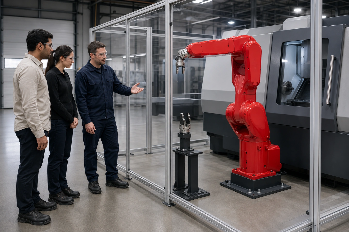 Application scenario illustration: fully generated, non-specific China-based factory staff and adult international visitors discuss a stationary six-axis robot, guarded CNC, visible quick-change wrist interface and tool stand from outside safeguarding.
A quick-change end-of-arm tooling record for one CNC should identify the selected master side, tool side, adapter, mating-interface revision and unique tool identity. It should keep approach and alignment, mating condition, lock command and independent feedback separate; list every service crossing the boundary; map each tool to its TCP, complete payload state and active program; and include the tool stand plus abnormal and maintenance states. Completing this record does not select a changer, prove compatibility or release operation.
Begin with the actual boundary, not the label “quick-change”
“Quick-change” describes a category, not a controlled interface. The record needs the selected master side and tool side, any adapter or mounting plate, the applicable mating-interface drawing revision, and a unique identity for the tool. Those details distinguish one physical combination from another that may look similar in a photograph.
Manufacturer examples show that locking arrangements, mounting patterns, media modules and tool-side coding can differ by product. The practical rule is simple: retain evidence for the selected components and their revision rather than transferring a feature from an unrelated changer. The CNC loading gripper design inputs can help define the installed tool context, while this checklist stays at the master-to-tool boundary.
Record approach, mating, command and feedback as separate fields
The robot's approach and alignment to the change position are not the same thing as the condition of the mating faces. A lock or unlock command is not the same thing as independent confirmation of the selected coupling state. If these are collapsed into one “changed” checkbox, it becomes difficult to see which evidence is missing after a tool or module change.
For each state, retain the selected manufacturer's documentation, the revision under review and the unresolved item. The project team must follow the selected manufacturer's coupling and confirmation conditions before leaving the change position. This page does not define those conditions or create a recovery sequence.
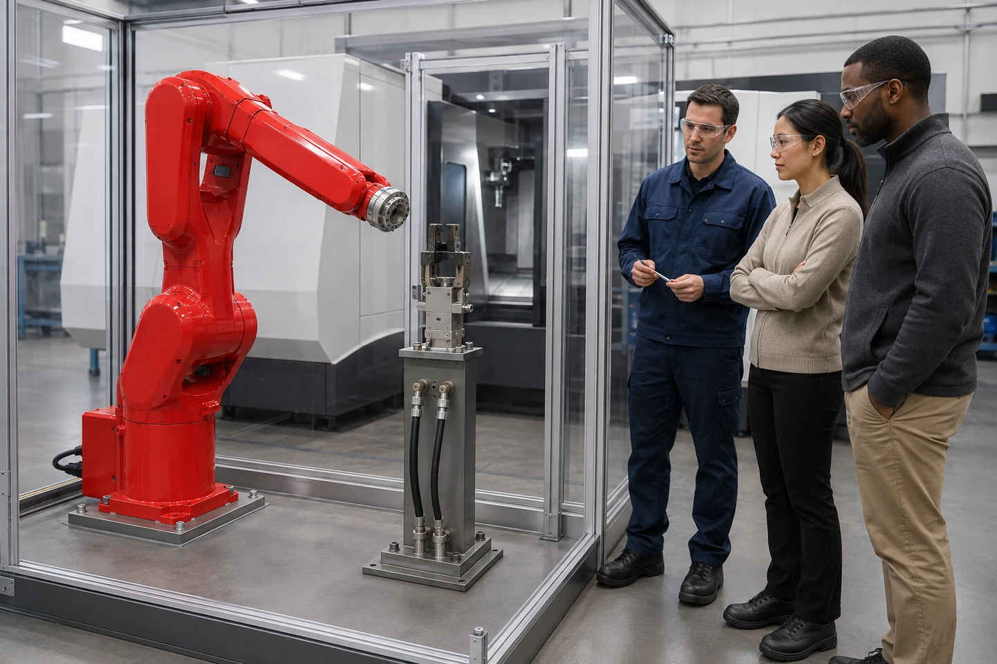 Application scenario illustration: the generated adults are discussing a technical record outside the safeguarded area. The image is not a real customer visit, completed change test, acceptance record or operational release.
Inventory every service that crosses the tool-change boundary
A tool changer can carry more than a mechanical connection. The controlled record should list any locking air, tool air or vacuum, electrical power, discrete signals, data and fluid service that crosses the selected boundary. Each service needs a corresponding connector or module identity, assignment, rating, isolation state and mating condition in the selected manufacturer documentation.
Do not prefill pinouts, pressures, voltages, ratings or port assignments from a generic layout. Services moving beyond the interface also need their own routing review; six-axis robot dress-pack routing is the relevant navigation path for that separate subject.
Map every tool identity to the right robot records
Tool identity should point to the correct TCP record, complete payload state and active program reference. TCP and payload are separate specialist records, not numbers to be calculated in this interface sheet. The useful question is whether the tool currently mounted and the tool actually called by the program point to the same controlled records.
After a change, reconcile the active tool and active payload used by the program. Use the six-axis robot payload checklist for manufacturer-specific load data and the CNC machine-tending interface checklist for the CNC-to-robot handoff. Neither navigation page turns this record into a compatibility decision.
The tool stand belongs in the interface record
The interface does not end at the wrist. A tool stand needs its own pickup and drop-off pose input, support and deflection basis, tool-present evidence, retained utilities, contamination exposure, and the complete robot-tool-workpiece path to and from the stand.
The stand review is not a reach study or a path validation. It makes the stand's role visible so that changes to the stand, tool, support or route can be carried into the appropriate next review. For one-CNC arrangement inputs, see the one-CNC reach-study checklist.
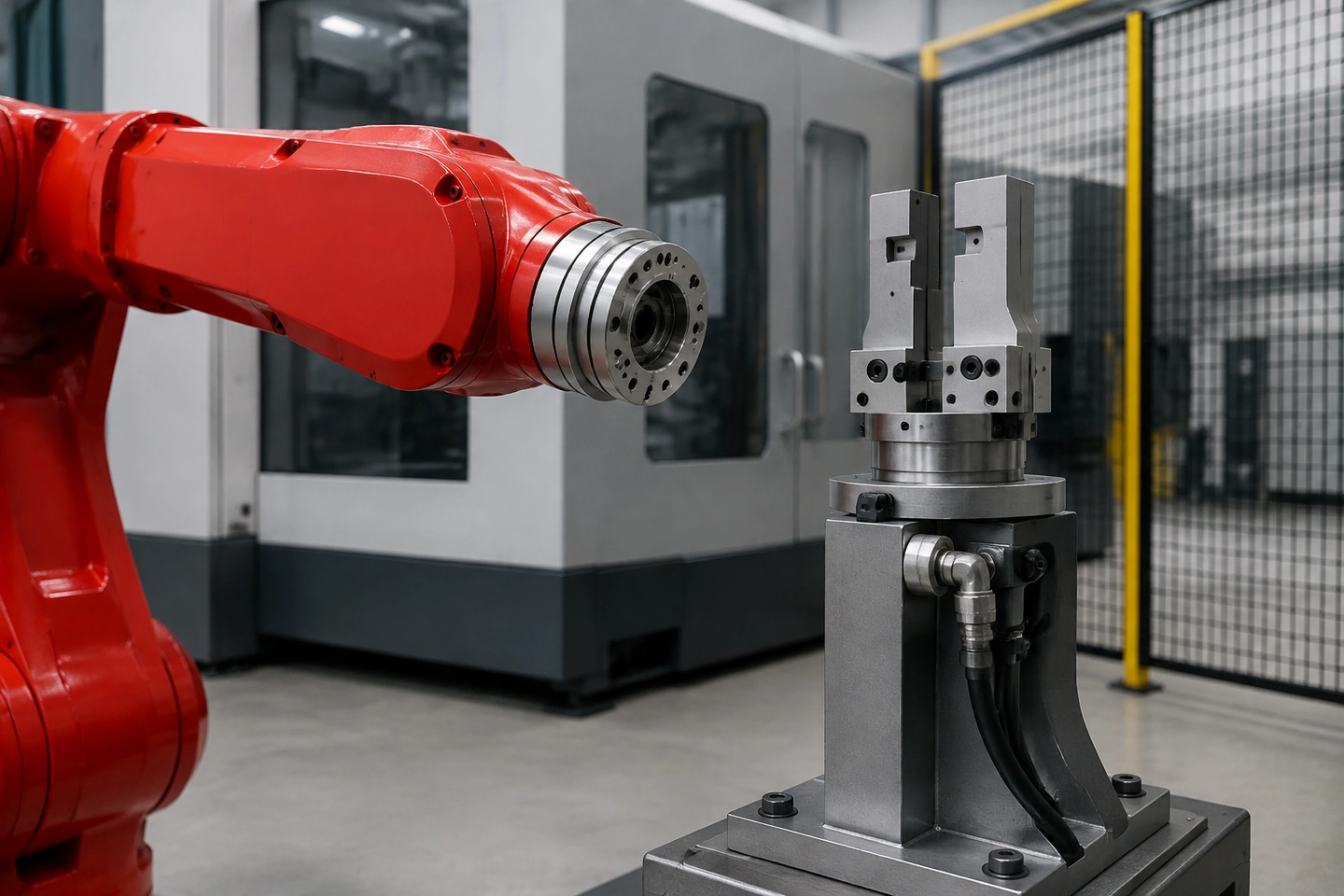 Application scenario illustration: this no-people technical detail contains no readable text, connector pins, ratings or diagram styling. It is not an engineering drawing, a capacity claim or proof that an interface is compatible.
Keep change and maintenance states visible
Normal coupling, uncoupling, abnormal or fail-safe conditions and maintenance must remain distinct reviewed states. A change to the tool, module, hose or cable route, stand, program or interface should retain its revision, evidence, owner and required recheck under the selected manufacturer's instructions and the cell's project process.
This is where an interface record becomes useful during handover: it preserves the facts that need follow-up without declaring that an abnormal condition is resolved or that the cell is safe. It does not replace risk assessment, maintenance procedures or project release.
Fillable quick-change EOAT interface record
| Interface element | Required controlled record | Selected manufacturer or revision evidence | Open item, owner and recheck |
|---|---|---|---|
| Master and tool sides | Enter selected identities | Enter document or revision | Enter open item |
| Adapter and mating face | Enter interface relationship | Enter drawing or revision | Enter open item |
| Lock or unlock command | Enter controlled state reference | Enter manufacturer evidence | Enter open item |
| Independent feedback | Enter confirmation reference | Enter manufacturer evidence | Enter open item |
| Each transferred service | Enter service identity and assignment | Enter module or connector evidence | Enter open item |
| Tool-to-TCP and payload mapping | Enter linked controlled records | Enter record references | Enter open item |
| Tool stand | Enter pose, support and presence inputs | Enter layout or revision | Enter open item |
| Abnormal and maintenance states | Enter state and recheck need | Enter applicable evidence | Enter open item |
For a broader application discussion, the single-machine CNC tending solution provides navigation to the one-machine context. It is not a selection or release result for any particular changer.
Frequently asked questions
Is “quick-change” enough to define the interface?
No. The selected master and tool parts, revisions, modules and unique tool identity need controlled records. A category name cannot identify the physical combination or its documentation.
Can lock command and confirmation share one field?
No. The command and independent feedback are distinct. Keeping them separate makes missing evidence and post-change rechecks visible.
Does this calculate TCP or payload?
No. It records the mapping from a tool identity to dedicated TCP and payload records. Those records must be checked through the selected robot manufacturer's methods and project process.
Does completion prove compatibility or safety?
No. Changer selection, mechanical compatibility, risk assessment, safety decisions and release remain specific to the selected equipment and project.
Sources and use boundary
This article uses only QX026-F01 through QX026-F06 and the fact records named in this task. ATI and SCHUNK material is used only to show why selected manufacturer documentation is controlling; no product feature, pattern, rating, module or behavior is transferred to QIXING.
Send the controlled interface inputs
For a QIXING project discussion, gather the selected master and tool documents, adapter drawing, module or connector records, tool identities, TCP and payload references, tool-stand inputs and unresolved states, then send the interface data. This request does not promise selection, compatibility, cycle time, safety or release.