Application Note / 2026-08-27
Frame-Mounted vs Integrated Gantry Robots for One-to-One CNC Machine Tending
A useful one-to-one gantry comparison starts with the CNC machine, workpiece route and project interfaces. This guide shows what is known from two published configurations and what still requires application review.
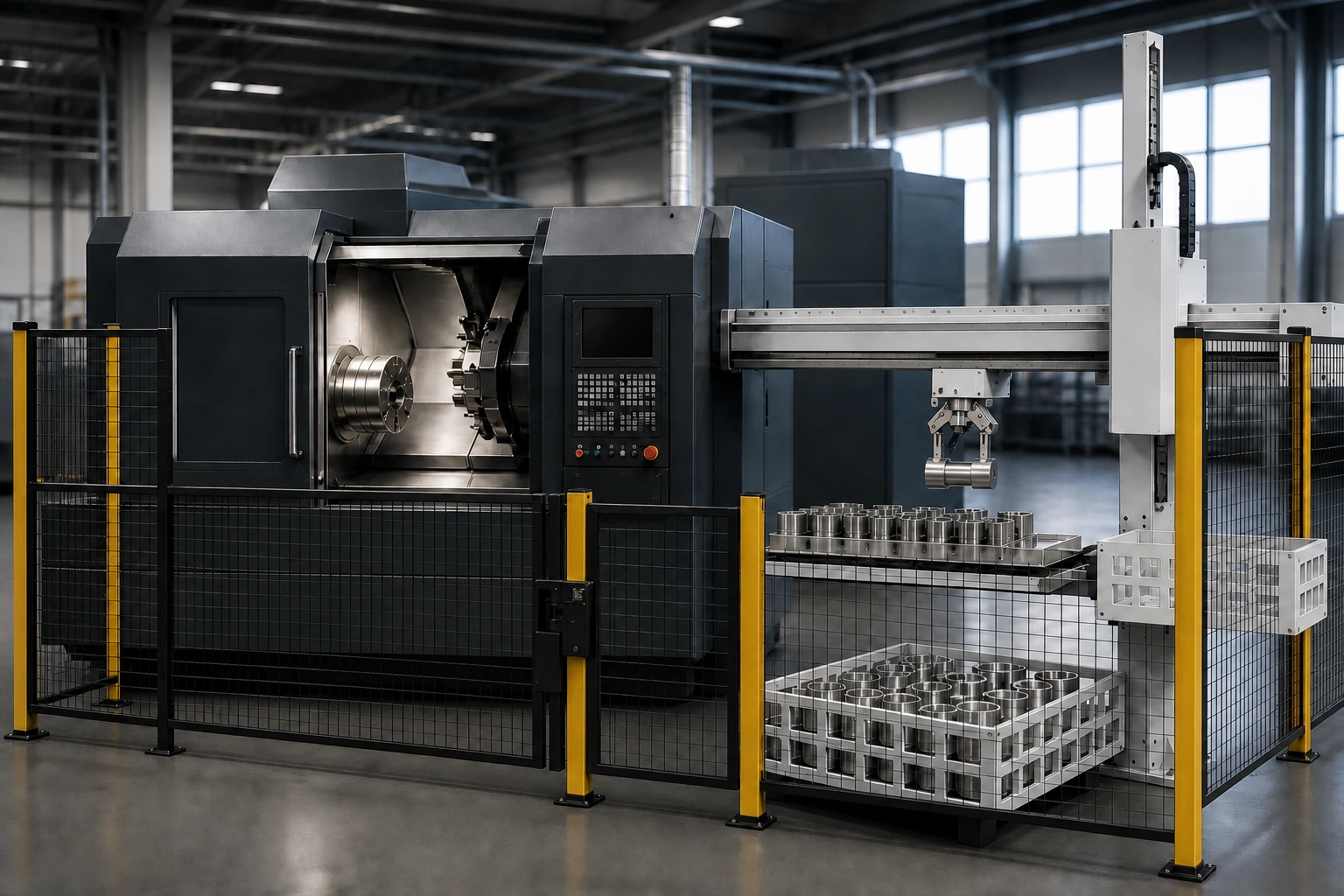 Application scene visualization / final layout subject to engineering review
The practical difference between a frame-mounted and an integrated one-to-one gantry robot cannot be reduced to a universal winner. For one CNC machine, the choice must be reviewed against the actual machine opening, loading direction, blank and finished-part positions, workpiece and gripper conditions, interfaces, guarding, maintenance access and available layout. Published configurations can define the two comparison points, but the final tooling, payload use, interfaces and layout remain application-specific.
Start with one CNC machine and one material path
A single-machine tending sequence organizes blank loading and finished-part unloading around one CNC machine. The published baseline path is material tray → gantry pick → CNC process → finished part. This sequence is a useful way to identify every handoff, but it is not a validated layout, cycle-time result or safety approval for a particular project.
Before comparing equipment, draw that path around the real machine. Mark the blank position, pick point, machine opening and finished-part position. The comparison then becomes an engineering question about installation and handoffs.
For a visual overview of the baseline sequence, see the single-machine CNC tending flow.
What “frame-mounted” means in this evidence set
In this article, “frame-mounted” refers specifically to the published QR4-1600 example. It is a one-to-one gantry robot installed above the machine tool. The current public manual lists effective strokes of 1,250 mm on X, 835 mm on Z and 575 mm on Y for the published QR4-1600 configuration.
Those values establish a model-specific reference; they do not confirm reach for another machine, workpiece or gripper. An application review still needs the machine envelope, door or skylight location, loading direction, workpiece transfer pose, gripper geometry, surrounding equipment and maintenance access.
Questions to review for the frame-mounted example
- Is the machine opening positioned and sized for the intended transfer path?
- What usable space exists above and around the machine after current accessories are included?
- Where can the material tray sit relative to the pick position and the machine opening?
- Can the proposed workpiece pose and gripper pass through the opening without an unverified assumption about clearance?
- Which interfaces and guarding conditions must be confirmed for the installation?
These are review questions, not evidence that a frame-mounted system is automatically compact, easier to install or suitable without modification.
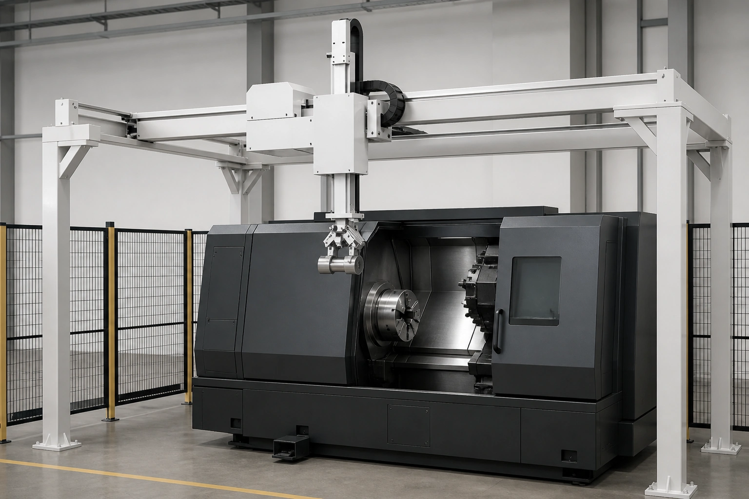 Application scene visualization / final layout subject to engineering review
What “integrated” means in this evidence set
Here, “integrated” refers specifically to the published QR4-2400 example. Public material describes an integrated one-to-one machine-tending structure and a quick-change tray gripper. The current public manual lists effective strokes of 2,080 mm on X and 1,000 mm on Z for the published QR4-2400 configuration.
The integrated description makes the tray relationship part of the review from the beginning. The engineering team still needs to examine blank presentation, finished-part return, replenishment direction, machine access, workpiece pose and interface requirements. A quick-change tray gripper is a published feature of this example; it does not by itself determine the final workpiece gripper, payload use or material arrangement for a project.
Questions to review for the integrated example
- Where will blanks and finished parts be presented within the proposed arrangement?
- How will operators replenish or remove material while respecting the planned safety boundary?
- Does the machine opening align with the intended approach and withdrawal direction?
- Which tooling, gripper and workpiece conditions must be validated before layout approval?
- What access is required for service, maintenance and material handling?
The answers depend on the real machine and production task. The integrated configuration should not be described as automatically smaller, faster, safer or simpler.
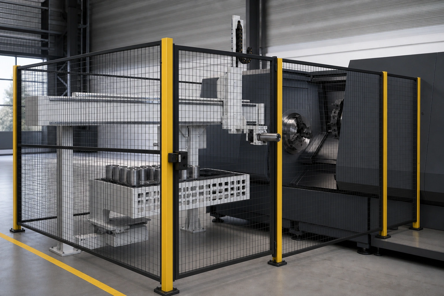 Application scene visualization / final layout subject to engineering review
Compare project conditions instead of searching for a universal winner
The most reliable comparison separates published evidence from open application questions. It also prevents model-specific information from becoming a general claim about every frame-mounted or integrated system.
| Review topic | Evidence available from the published examples | Still requires application validation |
|---|---|---|
| Configuration relationship | QR4-1600 is installed above the machine tool; QR4-2400 uses an integrated machine-tending structure | Fit with the actual CNC envelope, opening, surrounding equipment and service space |
| Material flow | Both are bounded examples for one-to-one tending around one CNC machine | Blank position, finished-part position, replenishment route and loading direction |
| Published motion reference | QR4-1600: X 1,250 mm, Z 835 mm, Y 575 mm; QR4-2400: X 2,080 mm, Z 1,000 mm | Actual reach with the proposed workpiece, gripper, transfer pose and machine geometry |
| Tooling | QR4-2400 public material describes a quick-change tray gripper | Final workpiece gripper, contact conditions, payload use and changeover method |
| Interfaces and recovery | The 2026 public manual lists synchronization, detection and recovery functions | Applicable model and configuration, machine interface, control sequence and project tests |
| Safety and access | The need for guarding and access can be included in the review | Complete risk assessment, safeguarding design, maintenance access and site acceptance |
Axis strokes are inputs to a comparison, not a selection result. A published value does not establish access to a specific chuck, door or tray position; the real transfer geometry also includes the workpiece, gripper, approach direction and machine opening. Likewise, a product image can show a configuration relationship, but it cannot confirm scale, clearance or site fit.
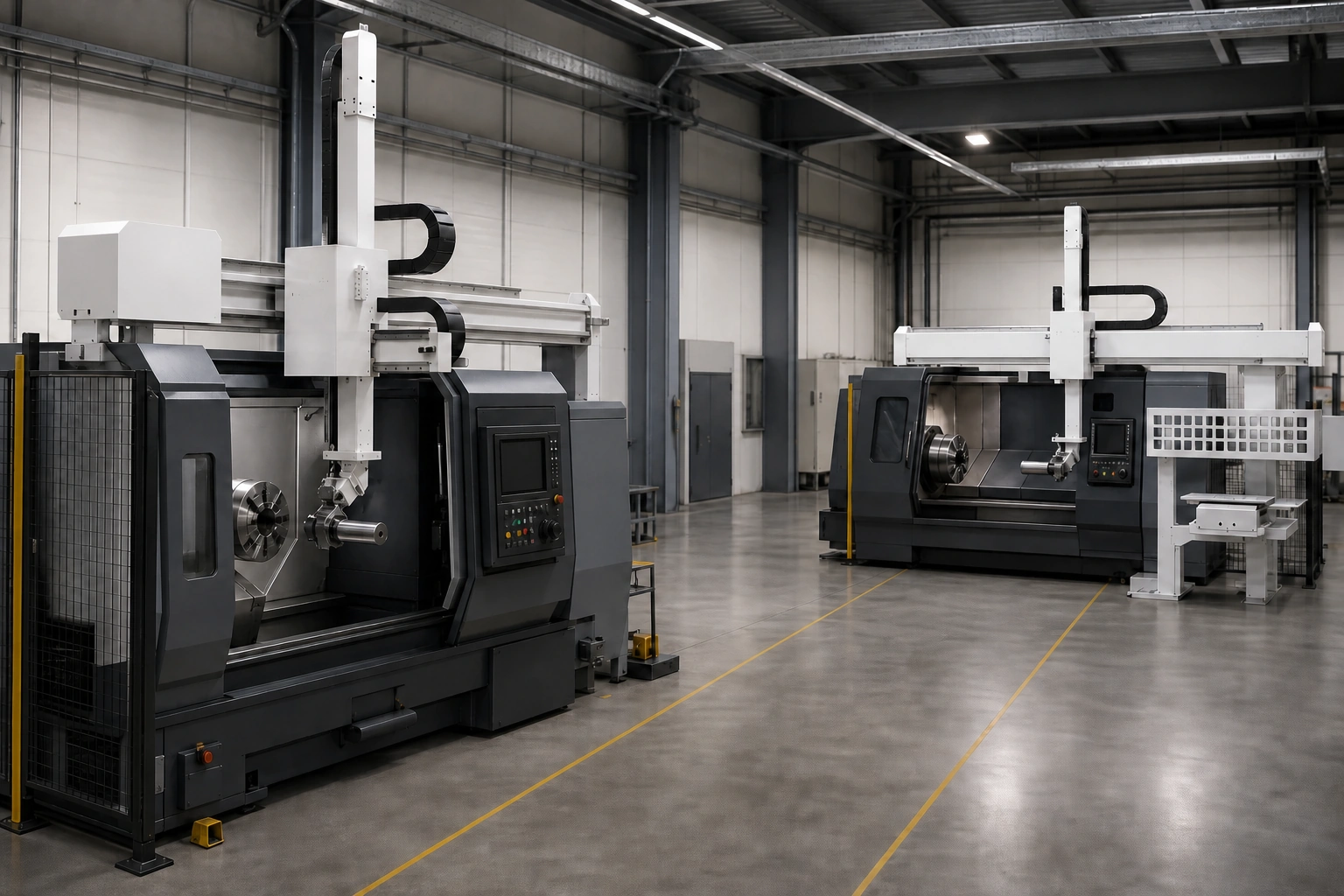 Application scene visualization / final layout subject to engineering review
Interfaces, handling functions and recovery remain project-specific
The public 2026 manual describes torque-monitored anti-collision, empty-grip detection, skylight or machine synchronization, one-click safe reset and program templates. These items may be used as prompts for an application checklist only. They are manual-listed capabilities subject to the applicable model, configuration and project validation.
They must not be treated as a safety certification, a complete risk assessment or a guarantee that a collision cannot occur. A real application review needs to identify machine states, opening logic, workholding sequence, response to an empty grip, permitted recovery actions and safeguarding. The implementation and validation scope must then be confirmed for the selected configuration.
For related context, see broader gantry architecture selection. That article covers a wider architecture decision; this comparison remains limited to two one-to-one examples for one CNC machine.
Decision framework for an application review
Use the following sequence before requesting a configuration recommendation.
1. Document the machine as installed
Provide the CNC model, an actual layout or dimensional drawing, machine envelope, opening and location, loading direction, accessories and service areas. Do not infer the complete installation from a model name.
2. Document blanks and finished parts separately
Record dimensions, weight, center of gravity, permitted gripping surfaces and transfer poses for both states. Note any change in accessible surfaces or balance after machining.
3. Mark every material position
Show where blanks enter, finished parts leave, trays sit and material is replenished. Include operator and maintenance access.
4. List interfaces and validation questions
Identify electrical and pneumatic conditions, machine states, opening logic, workholding controls, guarding requirements and recovery situations. Mark unconfirmed items as open questions.
5. Compare the configurations against the same input set
Apply the same machine, workpiece, material-flow and interface data to both examples. This makes the recommendation traceable to project conditions and avoids selecting a configuration from a product name or a single axis value.
FAQ
What is a frame-mounted one-to-one gantry robot?
Within this evidence set, it is represented by the QR4-1600, a published one-to-one gantry robot installed above the machine tool. This definition should not be generalized into claims about every frame-mounted design.
What is an integrated one-to-one gantry robot?
Within this evidence set, it is represented by the QR4-2400, which public material describes as an integrated machine-tending structure with a quick-change tray gripper. Final tooling, interfaces and layout still require application review.
Which configuration is better for a CNC lathe?
There is no evidence-bounded universal winner. The actual machine opening, workpiece, material positions, loading direction, tooling, interfaces, guarding, maintenance access and available layout must be reviewed together.
Can the published axis strokes determine the final selection?
No. The values apply only to the published QR4-1600 and QR4-2400 configurations. Actual reach and fit depend on the proposed gripper, workpiece pose, machine geometry, interfaces and final layout.
Request a one-to-one configuration review
To submit your machine and workpiece data, share the CNC machine layout and opening, raw and finished workpiece data, material positions, loading direction and interface requirements so QIXING can review the appropriate one-to-one gantry configuration.